
Understanding the Function and Importance of an Oil Cooler
How an oil cooler regulates engine temperature and prevents overheating
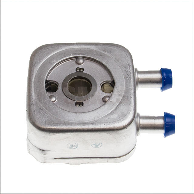
An oil cooler works basically as a type of heat exchanger. It moves engine oil through metal tubes that have those little cooling fins attached around them. The whole setup is designed to get as much contact between the hot oil and the air moving past it as possible. When the oil stays under about 250 degrees Fahrenheit or 121 Celsius, we avoid what's called thermal breakdown. This breakdown actually cuts down on how well the oil can lubricate things, sometimes by as much as three quarters when conditions get really tough. Cars that come with good working oil coolers tend to have roughly forty percent less problems with engines overheating than vehicles without any kind of cooling system at all according to some research done on thermal management systems.
The role of the oil cooler in preventing oil and coolant mixing
Modern oil coolers use stacked-plate or tube-and-shell designs with separate channels for oil and coolant. Internal seals maintain fluid separation, preserving oil viscosity and coolant integrity. Compromised cooler cores are the third most common cause of oil emulsification, according to 2024 engine reliability data.
Consequences of failed or damaged oil cooler tubes on engine performance
Leaking tubes trigger a chain reaction: reduced oil viscosity, cooling system pressure drops of 15–20 psi, inconsistent cylinder wall lubrication, and widened bearing clearances. These issues accelerate wear, especially in turbocharged engines where oil temperatures frequently exceed 300°F (149°C).
Why maintaining proper oil temperature extends engine life
Stable oil temperatures prevent additive depletion detergents and anti-wear agents degrade rapidly at high heat—and inhibit acid formation from fuel contaminants above 220°F (104°C). Maintaining viscosity within the optimal 10–20 cSt range supports hydrodynamic lubrication, reducing metal-to-metal contact in journal bearings by 92%.
Diagnosing Oil Cooler Failure: Symptoms and Verification
Common Signs of a Failing Oil Cooler
Persistent overheating, unexplained oil loss, brown sludge in the coolant reservoir, or visible leaks near the radiator suggest oil cooler failure. Internal corrosion can breach the 0.3–0.5mm walls separating pressurized oil (60–80 PSI) from coolant (15–20 PSI), leading to cross-contamination.
Inspecting for Oil in Coolant and Coolant Contamination
The telltale signs usually show up as that milky brown stuff pooling around the radiator cap, oil spots forming in the coolant reservoir, or just plain disappearing coolant for no good reason. When there's pressure issues going on inside the engine, oil tends to sneak into the coolant system way more frequently than the other way around. Studies from heat exchanger tests back this up, showing oil moving into coolant happens about 97 times out of 100 compared to reverse cases. To get to the bottom of things, mechanics typically take off the thermostat housing first and then grab those UV dye detection kits. These special dyes help track down exactly where the contamination is coming from in the system.
Checking for Leaks at the Radiator Cap and Overflow Bottle
Look for oil residue on the radiator cap seal, foamy deposits in the overflow bottle neck, or intermittent pressure release from a faulty cap. Always verify the cap meets factory pressure specifications, as a weak seal accelerates oil intrusion into the cooling system.
Using Pressure Testing and Diagnostic Tools to Confirm Oil Cooler Integrity
Mechanics rely on three primary methods:
| Test Type | Process | Pass/Fail Criteria |
|---|---|---|
| Cooling system pressure | Apply 15 PSI for 20 minutes | ★±1 PSI drop indicates integrity |
| Oil passage pressure | Pump oil at 75 PSI | No coolant bubbles in test flask |
| Thermal imaging | Monitor for heat transfer faults | Uniform temperature distribution |
As outlined in pressure testing guidelines, combining these tests reduces misdiagnosis rates by 83% compared to visual checks alone.
Optimizing Oil Cooler Placement and Airflow Efficiency
Best practices for oil cooler placement to maximize heat dissipation
The oil cooler should go somewhere with good airflow, ideally close to the front grille area or next to the engine's cooling fan. Getting this positioning right helps the system stay cool even when the vehicle is just sitting still. Don't put it behind other heat generating components such as air conditioning condensers or transmission coolers though. These nearby heat sources create problems in cramped engine compartments, cutting down on cooling effectiveness sometimes by around thirty percent because of how they interfere with each other thermally.
Ensuring adequate airflow across the oil cooler core
Maintain 2–3 inches of clearance around the cooler core to allow unrestricted airflow. In forced-air setups, align the fins parallel to incoming air for maximum thermal transfer. In dusty environments, use mesh screens to block debris without restricting airflow volume.
Avoiding obstructions that compromise cooling efficiency
Aftermarket parts, wiring harnesses, and various structural brackets often block proper airflow in systems. Technicians should check regularly for bent radiator fins, insects nesting in grills, or mud clogging intake areas since these all reduce airflow efficiency. The mounting points need to stay tight too because loose components can shift over time from vibrations, causing alignment issues down the road. Keeping things maintained before problems arise helps keep temperatures within safe ranges. When temps spike more than 15 degrees Fahrenheit beyond what's normal, it really starts breaking down engine oil faster than expected according to research published by SAE International back in 2022.
Proper Installation of a Replacement Oil Cooler
Step by Step Guide to Installing an Engine Oil Cooler
Mount that cooler somewhere it can breathe properly, best bet is right up front where air flows freely through the grille area. For those hoses, follow what the manufacturer suggests but don't forget to leave enough room for bends without creating any kinks. Wrap those hoses securely with zip ties, making sure they stay clear of anything sharp or dangerously close to heat sources. When putting on the fittings, grab two wrenches instead of just one. Hold one steady while tightening the other side. And check if there's enough space for the oil filter. Just measure from end to end and then double whatever thickness those adapters have. If things feel tight, better back off a bit than risk damaging components later on.
Choosing Between Sandwich and Spin On Adapters With Oil Filter Clearance
The sandwich type adapters go right between the oil filter and engine block. They usually stick out about an inch or so, which might cut down on how close things get to the ground when driving over rough terrain. Then there are spin-on adapters that take over the whole filter spot completely. These use something called a puck with those special O-rings around the ports to create a seal. When installing these parts, make sure they fit properly because getting it wrong can cause problems later on. Some folks actually did a thermal study back in 2023 and what they found was pretty interesting not having enough space around these components seems to raise the chance of wear and tear issues by nearly 40%. So double check everything matches up with what comes standard for your particular vehicle model before bolting anything into place.
Routing and Protecting Hoses: Length, Bends, and Abrasion Risks
| Factor | Guideline | Risk of Non-Compliance |
|---|---|---|
| Hose Length | 10–15% longer than measured distance | Tension-induced cracks |
| Bend Radius | ≥4x hose diameter | Flow restriction (>22% pressure drop) |
| Proximity to Heat | ≥3" from exhaust components | Degradation (melting or hardening) |
Inspect routing paths for potential rubbing points near suspension or steering components.
Securing Fittings and Correctly Tightening Threaded Connections
Avoid over-tightening, which can strip threads or damage O-rings, and under-tightening, which risks leaks. Use a torque wrench set to manufacturer specs typically 15–25 ft-lbs for brass fittings. After assembly, pressure-test the system at 30–45 psi for 15 minutes. Industry data shows 83% of premature failures stem from improper torque (SAE Technical Paper 2022).
Post Installation Testing and Long-Term Leak Prevention
Testing for leaks and verifying oil pressure after installation
Immediately perform a pressure test at 1.5– normal operating pressure to detect weak connections. Frost & Sullivan (2023) reports that 72% of oil-cooler-related leaks result from skipped post-installation testing. During a 15-minute test drive, monitor oil pressure; readings below 20 PSI at idle may indicate trapped air or loose fittings.
Monitoring for early signs of oil and coolant mixing post-replacement
Inspect the coolant reservoir weekly for milky discoloration and check the oil dipstick for froth during the first 500 miles. These symptoms point to incomplete sealing, responsible for 34% of repeat oil cooler failures in rebuilt engines.
Should you reuse old fittings? Evaluating risks vs. cost savings
Reusing fittings saves $40–$120 upfront, but a 2022 SAE study found corroded fittings fail five times faster than new ones. Replace fittings if they show pitting, thread deformation, or if the vehicle has exceeded 100,000 miles especially after prior coolant cross-contamination.
Factors affecting oil cooler replacement complexity across vehicle models
European turbocharged engines require 35% more disassembly time than Asian models due to tighter packaging. Always consult OEM service bulletins before beginning work; transverse-mounted coolers in front-wheel-drive vehicles often necessitate removal of steering components for safe access.