
 EN
EN
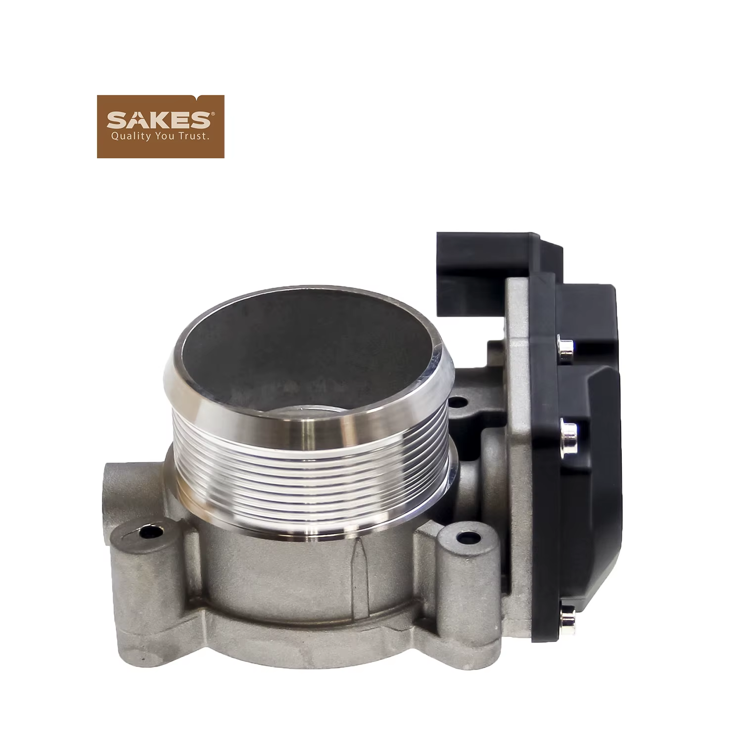
Throttle Body: Step-by-Step Methods for Testing Valve Opening and Closing Accuracy
The difference between replacing a throttle body and cleaning one often comes down to ten minutes of systematic testing. A technician who skips testing and replaces the unit may fix the symptom but leave money on the table — or replace a good component while the actual fault lies elsewhere. Structured testing isolates the problem to the throttle body itself or directs attention upstream to wiring, ECU, or accelerator pedal faults.
Preparation and Safety Before Testing
Testing a throttle body requires a diagnostic scan tool with live data graphing, a digital multimeter with back-probe leads, and basic hand tools for intake boot removal. Before any electrical testing, disconnect the battery negative terminal and wait five minutes for ECU capacitors to discharge. Position the vehicle on level ground with the parking brake engaged. Remove the intake duct for visual inspection but never insert fingers into the bore with ignition on — electronic throttle bodies can close with sufficient force to cause injury.
Three-Layer Testing Methodology
Layer One: Visual and Mechanical Inspection
Inspect the throttle body bore and plate edges using a flashlight. Carbon deposits appear as a dark ring on the bore wall where the plate edge rests at idle. Move the throttle plate manually by hand with the ignition off — roughness, sticking, or audible grinding indicates internal gear damage. Check the throttle body connector for corrosion, bent pins, or loose terminals. Wiggle the wiring harness near the connector while monitoring idle quality or scan tool readings when the vehicle is running — intermittent connection faults are notoriously difficult to reproduce during static testing.
Layer Two: Sensor Signal Voltage Testing
Back-probe the TPS signal wires on the throttle body connector. Two signal voltages should move in opposite directions as the pedal is pressed: Track 1 ranges from 0.5V closed to 4.5V wide open, while Track 2 mirrors from 4.5V to 0.5V. With ignition on and engine off, slowly press the accelerator pedal while watching both readings. Any voltage dropout — a sudden return to zero or spike to 5V — indicates a worn potentiometer track. The two signals should sum to approximately 5V at every position; a sum deviation exceeding 0.1V suggests a sensor fault.
Layer Three: Actuator Motor and ECU Command Testing
Using a scan tool, command the throttle body to open in 10% increments while observing actual versus commanded position. A lag exceeding 200 milliseconds between command and response indicates motor weakness or mechanical binding. Measure actuator motor resistance at the connector — values between 1 and 5 ohms are typical, while an open circuit or short confirms motor failure. During the sweep test, listen for clicking or grinding sounds from the throttle body — these indicate damaged reduction gears that cannot be repaired.
A Real-World Case: Misdiagnosed Throttle Fault
A 2015 Audi A3 arrived with a P0638 code and intermittent limp-home mode. The previous shop had replaced the throttle body — but the code returned after 200 kilometers. On deeper investigation, the technician back-probed the TPS signal at the ECU connector and compared readings to the same signals measured at the throttle body. A 0.3V difference indicated resistance in the wiring harness — a partially broken wire inside the insulation near a factory harness bend point. The throttle body itself was functioning correctly. Sakes Auto Parts replacement assemblies are tested against OE signal specifications, but no component can compensate for upstream wiring faults. The wire was repaired, and the original symptom resolved without replacing the throttle body again.
Practical Testing Protocol for Workshop Efficiency
Document all test results in a standardized format: TPS voltage at idle, 25% pedal, 50%, 75%, and WOT for both signal tracks. Photograph carbon condition before and after cleaning. Record motor resistance and sweep test smoothness. This documentation serves warranty evidence and builds vehicle-specific diagnostic baselines — technicians who skip it often repeat the same tests months later without remembering previous results. Throttle body assemblies from Sakes Auto Parts include OE specification data sheets that assist with comparative diagnostics during installation.
Frequently Asked Questions
Can I test a throttle body without a scan tool?
Basic voltage testing with a multimeter at the TPS signal wires can identify dead spots, but live-data graphing provides more complete diagnostic information. A throttle body sweep test using a scan tool shows response speed and position accuracy that static voltage tests cannot reveal.
What voltage should a throttle position sensor read at idle?
Track 1 typically reads 0.5-0.7V at closed throttle, while Track 2 reads approximately 4.3-4.5V. The two voltages should sum to roughly 5V. Any deviation from these ranges on a throttle body suggests sensor wear requiring further investigation.
How do I know if the throttle actuator motor is failing?
Measure motor resistance at the connector — 1-5 ohms is normal. During a scan tool sweep test, listen for grinding noises and watch for delayed response between commanded and actual position. A failing throttle body actuator often produces intermittent codes before complete failure.
Why does my throttle body test fine but still cause problems?
Intermittent faults occurring only at specific temperatures or after extended driving may pass static bench tests. Road-testing with live data logging captures these conditions. A replacement throttle body from Sakes Auto Parts is tested across its full operating range, reducing the likelihood of intermittent issues.
Should the throttle plate move freely by hand?
With the ignition off, the plate should move smoothly through its full range with light, even resistance. Binding, sticking, or a gritty feel indicates internal gear or bearing damage. A throttle body showing mechanical roughness during manual testing requires replacement.
How long does a complete throttle body test take?
A thorough three-layer test — visual, sensor voltage, and actuator sweep — takes approximately 20-30 minutes for an experienced technician. Rushing the test or skipping live-data verification of a throttle body increases the risk of misdiagnosis and unnecessary parts replacement.